Displacer switches – single, dual and tri-switch series

Downloads

Displacer switches – single, dual and tri-switch series


Single-Stage Switches

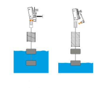
Series A10 displacer type level measurement units are wide differential units calibrated to actuate as a liquid level reaches a given displacer and to deactuate when the level reaches a second displacer. Single stage, wide differential displacer switches are factory calibrated yet field-adjustable to operate over a wide level differential band.

The minimum differential band is approximately 6 inches (152 mm) in water and varies somewhat with liquid specific gravity. The maximum differential is determined by the length of the displacer suspension cable. Series A15 units are calibrated to operate over a narrow level differential band and are ideally suited for liquid level alarm applications on either high or low level.

Dual-Stage Switches

Series B10 displacer type level measurement units are wide differential tandem switches that are factory calibrated with a choice of several switch operating sequences designed to meet virtually any application.

Series B15 units are narrow differential tandem switches that are factory calibrated. Each switch actuates at a different level.

Tri-Stage Switches

Series C10 displacer type level measurement units utilize three electrically separate control signals in a selected sequence in response to liquid level changes.

Series C15 units are wide differential switches with a choice of several operating sequences combining wide and narrow level differential and are factory calibrated.

Displacer switches

Technology

Displacer switch operation is based upon simple buoyancy, whereby a spring is loaded with weighted displacers, which are heavier than the liquid. Immersion of the displacers in the liquid results in buoyancy force change, changing the net force acting on the spring. The spring compresses as the buoyancy force increases.

A magnetic sleeve is connected to the spring and operates within a non-magnetic barrier tube. Spring movement causes the magnetic sleeve to move into the field of a pivoted magnet, actuating a switch mechanism located outside the barrier tube. Built-in limit stops prevent over stroking of the spring, under level surge conditions.

  • Displacers adjustable at any point along the suspension cable
  • 20 feet (6 meters) suspension cable standard
  • Anti-surge design eliminates the possibility of switch shortcycling
  • Flanged or threaded mounting available
  • Easy installation
  • Field adjustable set point and switch differential
  • NACE models
  • Floating rooftop models
  • Choice of switch mechanism: ◦ Dry contact ◦ Hermetically sealed ◦ Pneumatic
  • Choice of switch mechanism enclosure: ◦ TYPE 4X/7/9 Class I, Div. 1, Groups C & D, polymer coated aluminum ◦ TYPE 4X/7/9 Class I, Div. 1, Group B, polymer coated aluminum or cast iron ◦ NEMA 1, carbon steel for pneumatics
  • Choice of displacers: ◦ Porcelain ◦ 316 Stainless steel ◦ Karbate ◦ Brass

Options

  • Electric or pneumatic switch mechanisms and enclosures
  • Displacer cable length
  • Materials of construction
  • Tank connection
  • Floating roof detection
  • PROOF-ER® ground checker control
Chemical
  • Ammonia storage
Common applications
  • Level: Containment & drainage sumps
  • Level: Process & field storage tanks
Crude oil
  • Process & Field storage tanks
  • Production Fluid Storage
  • Wellstream separation
Natural gas
  • Compressor Waste Liquid
Nuclear power
  • Containment & drainage sumps
  • Cooling tower basins
  • Cooling tower intake & basin levels
  • Emergency coolant tanks
  • Liquid waste storage
  • Scram discharge volume tanks
  • Spent fuel pools
  • Turbine steam generators
Petroleum refining
  • Diesel fuel storage tanks
Power generation
  • Ammonia storage
  • Condensate storage
  • Cooling tower basins
  • Cooling tower intake & basin levels
  • Fuel oil storage
  • Water services
Pulp & paper
  • Mill water storage
Renewable energy
  • Biofuel
  • Biogas
Water & wastewater
  • Filter tank level
  • Lift station pump control
  • Water services
  • Water storage tanks

Operation is based upon simple buoyancy, whereby a spring is loaded with weighted displacers, which are heavier than the liquid. Immersion of the displacers in the liquid results in buoyancy force changing to net force acting on the spring. The spring compresses as the buoyancy force increases.

A magnetic sleeve is connected to the spring and operates within a non-magnetic barrier tube. Spring movement causes the magnetic sleeve to move into the field of a pivoted magnet, actuating a switch mechanism located outside the barrier tube. Built-in limit stops prevent over stroking of the spring, under level surge conditions.

ATEX Ex d, Ex ia
CCOE Ex d
CSA XP
FM XP
EAC (GOST) Ex d, Ex ia
IEC Ex d, Ex ia
Inmetro Ex d
Korea Ex d
NEPSI Ex ia
SIL SIL 2 (1oo1)
Marine Lloyd’s Register of Shipping (LRS)
TÜV/DIBt WHG § 63, overfill prevention

Other approvals are available.

+ Features
  • Displacers adjustable at any point along the suspension cable
  • 20 feet (6 meters) suspension cable standard
  • Anti-surge design eliminates the possibility of switch shortcycling
  • Flanged or threaded mounting available
  • Easy installation
  • Field adjustable set point and switch differential
  • NACE models
  • Floating rooftop models
  • Choice of switch mechanism: ◦ Dry contact ◦ Hermetically sealed ◦ Pneumatic
  • Choice of switch mechanism enclosure: ◦ TYPE 4X/7/9 Class I, Div. 1, Groups C & D, polymer coated aluminum ◦ TYPE 4X/7/9 Class I, Div. 1, Group B, polymer coated aluminum or cast iron ◦ NEMA 1, carbon steel for pneumatics
  • Choice of displacers: ◦ Porcelain ◦ 316 Stainless steel ◦ Karbate ◦ Brass

Options

  • Electric or pneumatic switch mechanisms and enclosures
  • Displacer cable length
  • Materials of construction
  • Tank connection
  • Floating roof detection
  • PROOF-ER® ground checker control
+ Applications
Chemical
  • Ammonia storage
Common applications
  • Level: Containment & drainage sumps
  • Level: Process & field storage tanks
Crude oil
  • Process & Field storage tanks
  • Production Fluid Storage
  • Wellstream separation
Natural gas
  • Compressor Waste Liquid
Nuclear power
  • Containment & drainage sumps
  • Cooling tower basins
  • Cooling tower intake & basin levels
  • Emergency coolant tanks
  • Liquid waste storage
  • Scram discharge volume tanks
  • Spent fuel pools
  • Turbine steam generators
Petroleum refining
  • Diesel fuel storage tanks
Power generation
  • Ammonia storage
  • Condensate storage
  • Cooling tower basins
  • Cooling tower intake & basin levels
  • Fuel oil storage
  • Water services
Pulp & paper
  • Mill water storage
Renewable energy
  • Biofuel
  • Biogas
Water & wastewater
  • Filter tank level
  • Lift station pump control
  • Water services
  • Water storage tanks
+ Operating principle

Operation is based upon simple buoyancy, whereby a spring is loaded with weighted displacers, which are heavier than the liquid. Immersion of the displacers in the liquid results in buoyancy force changing to net force acting on the spring. The spring compresses as the buoyancy force increases.

A magnetic sleeve is connected to the spring and operates within a non-magnetic barrier tube. Spring movement causes the magnetic sleeve to move into the field of a pivoted magnet, actuating a switch mechanism located outside the barrier tube. Built-in limit stops prevent over stroking of the spring, under level surge conditions.

+ Approvals
ATEX Ex d, Ex ia
CCOE Ex d
CSA XP
FM XP
EAC (GOST) Ex d, Ex ia
IEC Ex d, Ex ia
Inmetro Ex d
Korea Ex d
NEPSI Ex ia
SIL SIL 2 (1oo1)
Marine Lloyd’s Register of Shipping (LRS)
TÜV/DIBt WHG § 63, overfill prevention

Other approvals are available.

JOLAC ENGINEERING SDN BHD (“JOLAC”) was incorporated as private limited company in Kuala Lumpur, Malaysia under the Companies Act 1965 on 16th December 1982.