 Definitions
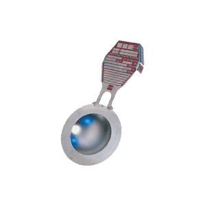
The disk relieves overpressure by reversing and snapping against knife blades located in the Safety Head cutting the disk into four petals.

Definitions
The disk relieves overpressure by reversing and snapping against knife blades located in the Safety Head cutting the disk into four petals.
Closer Margin Between System Design and Operating Pressure
The RB-90 Rupture Disk (Bursting Disc) enables systems to be operated at pressures up to 90% of the tagged burst pressure … as compared to a maximum of 70 to 80% for tension loaded solid metal and composite disks.
Existing equipment can now operate closer to its maximum allowable working pressure (MAWP).
Cuts Costs of New Systems
Only a 10% margin is needed between system operating pressure and the reversal pressure of an RB-90 Disk. This means the design pressure of a vessel, protected by the RB-90, can be closer to its operating pressure than one protected by relief devices requiring a 20 to 30% margin.
Longer Service Life
The RB-90 Rupture Disk (Bursting Disc) will last ten or more times longer than conventional prebulged disks in static or positive pressure cycles… 100 or more times longer in pressure-vacuum cycling service.
Less Affected by Fatigue and Creep
RB-90 disks are installed with the convex side toward the process and have compression loading. Conventional disks are installed with the concave side toward the process and are under tension loading. Disk metals under compression are much less affected by fatigue and creep.
No Vacuum Supports Required
RB-90 Disk metals are thicker than those used in conventional solid disks of the same size and pressure rating, so vacuum supports are not required. The RB-90 disk can also withstand high back pressure without damage.
Product Buildup is Reduced
RB-90 disks resist product buildup. Only the smooth convex side is exposed to system contents. The vacuum support under a conventional disk has an irregular surface which tends to allow a much faster product buildup. The use of RB-90 disks therefore cut maintenance costs by greatly extending the length of time between Safety Head disassemblies for cleaning.
Designed for Minimal Fragmentation
The RB-90 Rupture Disk (Bursting Disc) has four razor sharp blades that cut the disk into four equal segments without fragmentation. No process contamination by metal.
SPECIFICATIONS FOR STANDARD RB-90 RUPTURE DISKS Min/Max Disk Pressure Rating at 72o F. (PSIG) Disk Material
|
|
|
|
|
|
|
|
|
|
|
|
|
|
|
|
|
|
|
|
|
|
|
|
|
|
|
|
|
|
|
||
Manufacturing Design Ranges
EXAMPLE:
If a 100 psi burst pressure RB-90 disk is ordered with a zero manufacturing range, the disk will be tagged 100 psi burst pressure.
If a similar RB-90 Disk is ordered with a 10% manufacturing design range, it may be tagged at any pressure between 90 psi and 100 psi.
Burst Tolerances
Burst tolerances are the average variation from the above marked burst pressure.
Disk marked above 40 psig ± 5%
Disks marked 40 psig
and below ± 2psi
Service Conditions
Recommended for gas service only. For longer service life and lower maintenance, the STA-SAF® System (Type S-90, JRS and RLS) or SURE-SAFTM (Type CSR) is recommended. Refer to Catalogs 77-4001 and 77-4009
Specifications for RB-90® Reverse Buckling Rupture Disks
BS&B reverse buckling rupture disks (bursting discs) listed on the following chart are standard. Disks with higher or lower bursting pressures than those listed and in other materials may be available on special order. Consult factory with your application details.
Maximum temperature ratings have two sets of figures. Temperatures shown in black are °F., those in red are °C.
|
||
Non-Standard Materials PSIG
|
|
|||||||
The RB-90 Rupture Disk (Bursting Disc) is ideal for primary relief either by itself or installed at the inlet of a safety relief valve. The RB-90 complies with Section VIII Division 1, Paragraphs UG 125 through 134 of ASME Code.
RB-90 Reverse Buckling Disk. Pressure on CONVEX side of disk and patented seating design puts compression loading on disk metal. Four razor-sharp knife blades cut metal into four equal sections when reverse buckling occurs, providing complete opening without fragmentation.
To control accurate reversals, the RB-7R Safety Head utilizes a patented offset shoulder, machined radius and bite-type seal.
Guides to RB-90 Applications in a Wide Range of Services
Acceptable
1.Where the RB-90 is located in gas phase,
Non Acceptable Applications
1.Where the RB-90 is located in an all liquid system (except
those involving the release of a large volume of liquid immediately should overpressure occur).
Advantages of Installing Rupture Disks Under Safety Relief Valves
. Zero process leakage to the atmosphere
. Longer periods between major overhauls
. Valves can be tested in place
. Less expensive trim material can be used
. Valve life is extended by isolating corrosive fluids from internal valve parts.
RB-90 Reverse Buckling Safety Head mounted at inlet of a safety relief valve. This arrangement permits testing of a valve as shown without disassembly or process shutdown.
On all RB-90 disks, except aluminum, a system pressure of 50% or more of disk rating should be held on the convex side of the disk during valve testing to allow a testing pressure of 110% of disk rating to be applied.
CAUTION! If these conditions on differential pressure are not followed closely, laboratory tests indicate that performance rating of disk may be progressively reduced up to a maximum of 10% when disk is required to function.
RB-7R Bolted Type Safety Heads with RB-90 Reverse Buckling Disks
Type RB-7R QUIK-SERT SAFETY HEAD with side-mounted screws and bars.
RB-90 Rupture Disks can only be used in BS&B RB Type Safety Heads to guarantee correct burst pressures.
RB-90 Safety Heads require preassembly of reverse buckling disk in RB-90 flanges to assure proper seating. Standard RB-90 inlet and outlet flanges are flatfaced. Ring joint, raised face and tongue-and-groove facings are available.
Standard knife blade material is heat treated stainless steel.
Bolting Torque is Critical in the RB-90® Design
If bolting torque is too low in an RB-90 assembly, or if the compression load slacks off over a period of time because of a cold flowing gasket, a low pressure reversal can occur. So, select a gasket material that has a minimum tendency to relax in service.
Follow the torque values included in the installation instructions packed with each disk.
If the RB-90 Safety Head is located on a glass-lined outlet nozzle and minimum torque specified can damage lining, use the RB-7FS assembly. This condition requires only enough torque on bolting of mating flange to seal and hold gaskets on one or both sides of assembly. The RB-7FS assembly has enough capscrew bolting to provide the required holding force.
Accessories take the work out of installing RB-90 Safety Heads. See Union/Bolted/QUIK-SERT Safety Heads catalog for illustration of jack screws, eye bolts, baffle plate, gauge tap, full diameter preassembly.
Jack Screw specifications for RB-90 Safety Head Assembly RB-7R are the same as for QUICK-SERT Assembly FA-7R.
Standard RB-90 Safety Head Assemblies
Assembly RB-7R
Easiest to install and remove from service. For services allowing the use of reduced diameter Safety Head flanges. Disk is installed between two reduced-diameter flanges and preassembled with recessed cap screws or side-mounted screws and bars. Safety Head assembly nests between studs of the ANSI companion flanges.
Assembly RB-7FFTM
For services where released product can be vented to atmosphere harmlessly. Disk is installed between two full-diameter flanges and preassembled with recessed cap screws. Safety Head assembly bolts to ANSI flange. Outlet is free vented.
Assembly RB-7FSTM
For applications where product buildup requires periodic cleaning and Safety Head assembly must be removed without breaking disk seal or disturbing the bolting torque. Disk is installed between two full diameter flanges and torqued with recessed cap screws
RB-90 Safety Head Specifications
150# ANSI (275# Max. at -20o F to + 100o F)
300# ANSI (720 Psi Max. @ -20o F to + 100o F)
1 ” through 3″ – Same as 600# ANSI Group
| 2 11/16 | ||||||
| 3 7/16 | ||||||
| 4 7/16 | ||||||
| 5 1/8 | ||||||
| 5 7/8 | ||||||
600# ANSI (1440 Psi Max. at – 20o F to + 100o F)
NOTE: For dimensions of larger units not shown, consult Factory.
NOTE: Products, specifications, and all data in this literature are subject to change without notice. Questions regarding product selection and specifications for specific applications should be directed to BS&B, Attn: Customer Service Dept.